Slurry Pump
Slurry Pump
In general, the pump refers to a device that energizes the fluid and causes it to move from one point to another. Fluid-transported energy consists of kinetic compressive energy and potential. Classification of pumps based on various factors such as how to transfer energy to fluid, type of fluid, materials used in pump construction, etc. It takes place.
contents
The oldest devices that have been used to meet the needs of humans from the distant past are pumps that from several thousand years ago, from small to large and simple to its progress, first in the field of agriculture and water transfer from the depths of the earth to its surface and then with the advancement of science and industry and technology in all industrial areas has found its place. Even in a conventional car, several of them are used for many cases such as water pumps, oil pumps, gas stations, salted glass pumps, etc. . It is used and can truly be claimed that the industry is minus zero pumps and can not exist.
Pumps are widely used in the industry to provide cooling and lubrication services, fluid transfer for processing and propulsion in hydraulic systems. In fact, most manufacturing plants, commercial buildings and municipalities rely on pumping systems for their day-to-day operations. In the manufacturing sector, pumps provide 27% of the electricity used by industrial systems. In the commercial sector, pumps are mainly used in heating, ventilation and air conditioning (HVAC) systems for water supply for heat transfer. Municipalities use pumps to transport and rectify water and sewage and to drain land. Since they serve these diverse needs, pumps have sizes ranging from one horsepower to several thousand horsepower.
Pumps have different types in addition to a wide range of sizes. They are categorized by the method of adding energy to a fluid: positive displacement pumps with direct fluid pressure. Centrifugal pumps (also called “rotodinamic pumps”) increase fluid velocity and convert this kinetic energy into pressure. Among these classifications, there are different subsets. Positive displacement pumps include pistons, screws, sliding blades and rotary types. Centrifugal pumps include axial (propeller), mixed flow and radial. Many factors are decisive for choosing the pump type for an application. Often different types of services provide the same requirements.
Pump reliability is important – often critical. In cooling systems, pump failure can lead to overheating of equipment and catastrophic damage. In lubrication systems, insufficient pump performance can destroy equipment. In many petrochemical and electricity plants, pump failure can significantly reduce productivity.
Pumps are essential for the daily operation of many facilities. The tendency to promote the performance of protective pumps estimates to ensure that the system’s requirements are met in any circumstances. In order to ensure that the pumps are large enough to meet the system’s requirements, engineers often ignore the high cost of pumps, and on the other hand eliminate security risks by adding more pump capacity. Unfortunately, this increases the cost of system maintenance. In addition, giant pumps typically require more frequent maintenance than pumps of normal size. Excess flow energy increases the wear and tear of system components, causing damage to the valve, stress to the pipe and noise of the operation of the surplus system.
Pumping System Components
The usual pumping systems consist of 5 basic components: pumps, primary confidantes, tubes, valves and final equipment (such as heat exchangers, tanks, and hydraulic equipment). A conventional pumping system and its components are shown in Figure 1.
Help:
A= pump
B= Surface Indicators
C= tank, liquid storage
D= Pump Engine
E= Motor Controller
F= Throttle Valve
G= Shortcut Valve
H= Heat Exchanger
I= Instrumentation Line
J=Pipe Discharge Pump
K= Tube suction pump
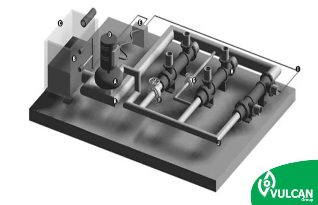
Typical pumping system components
Types of pumps
Pumps are available in a wide range of types, sizes and materials, they can be widely classified into two categories – positive displacement and centrifugal. These categories relate to the way in which the pump adds energy to the working fluid. Positive displacement pumps push the fluid with a falling volume, essentially squeezing a value of fluid equal to the displacement volume of the system with each piston impact or shaft rotation. Centrifugal pumps work by adding kinetic energy to a fluid using a rotating propeller. As the flow drops in the pump spreader, the kinetic energy of the fluid is converted to pressure.
Although two positive and centrifugal displacement pumps can be used in many applications, centrifugal pumps are more common because they are simple and safe and require little maintenance and have a long working life. Centrifugal pumps usually suffer less erosion than positive displacement pumps and require less replacement. Although mechanical packaging or seals must be replaced periodically, this usually requires less cost and time. Centrifugal pumps can also operate in a range of conditions. The risk of damage caused by inappropriate valve position is low if precautions are taken.
Centrifugal pumps have a variable flow/pressure relationship. A centrifugal pump reduces the flow against the high pressure of the system while it operates against the low pressure of the system.
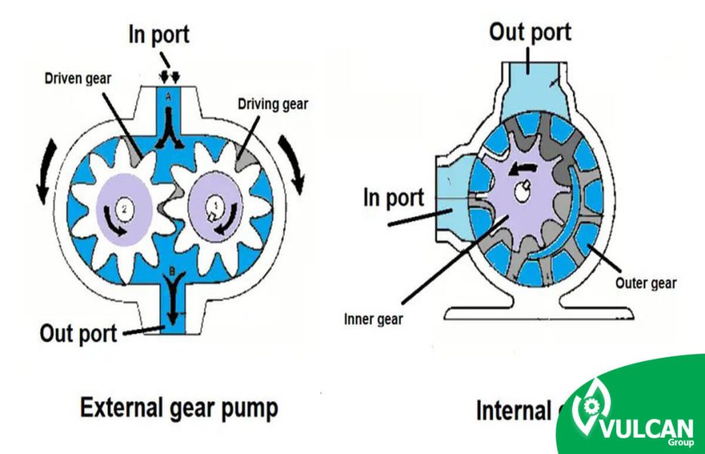
In contrast, positive displacement pumps have a constant displacement volume. As a result, their production flow rates are directly proportional to their speed. Their generated pressure is determined by the system’s resistance to this flow. Positive displacement pumps have operational advantages that make them functional for specific applications. These pumps are usually more suitable for the following conditions:
- The fluid used is very viscous.
- A system that requires high pressure, and low pump flow performance.
- The pump must have the ability to fill itself.
- The fluid used should not have high shear forces.
- The flow must be measured or precisely controlled.
- Pump efficiency is very valuable.
In general, the division of pumps based on various factors such as the way of transferring energy to the fluid, type of fluid, materials used in the manufacture of pumps, etc. It takes place.
The classification of pumps in terms of procedures and principles of work are divided into two general categories:
A- Pump Dynamic Kinetic Pump Pumps
B- Pumps Displacement Positive type pumps
Pump Dynamic Kinetic Pump Pumps
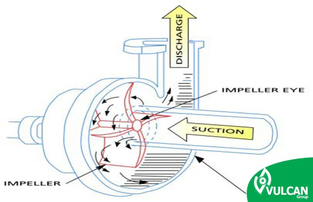
The basis of this type of pump is based on adding kinetic energy to the fluids, which is carried out in most of the speed or movement of the fluid through the pump mechanism, which are propellers, which converts some of the kinetic energy generated inside the pump and another amount in the pump outlet to compressive energy. These pumps are classified in the following general categories:
1- Radial current pumps or centrifugal pump center grizzly
2- Mixed Current Pump Flow Pump Mixed
3- Pump Flow Axial Axial Axial Axial Current Pump Pump
4- Pump Peripheral Pump environmental flow pumps
Pumps Displacement Positive Displacement Type Pumps
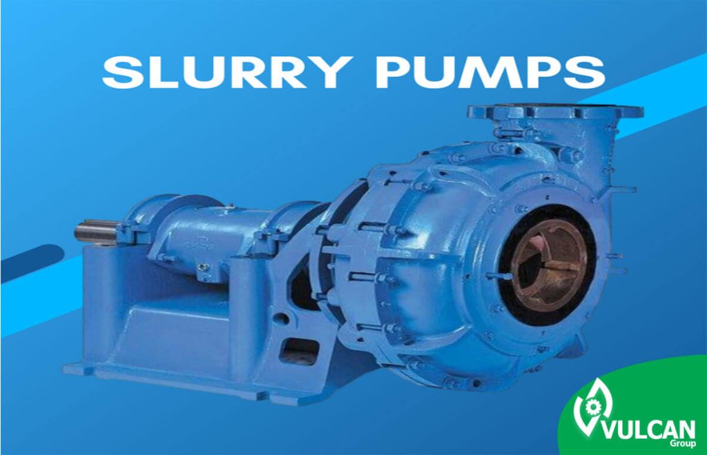
sllury pumps or material handling pumps
slurry can be a mixture of any kind of fluid with some solid particles. A combination of type, size, shape and amount of solid particles along with the nature of fluid transfer characterize the exact characteristics and properties of slurry flow.
slurry Specifications
Widely, slurry can be divided into two general saturated and unsaturated groups. Polyunsaturated slurry contains very soft particles that can create a stable and uniform mixture that increases fluid viscosity. These slurries usually have few abrasion properties, but given that they usually do not behave the same as conventional fluids, special attention should be paid when choosing a pump. When the solid particles in the slurry are enough to cause fluid behavior to distance itself from the behavior of the ordinary fluid, they are called non-Newtonian fluids.
Saturated slurry is composed of rough and neutral particles that tend to create a non-uniform mixture, so special attention should be paid to flow and power calculations. These rough and rough particles have many abrasive properties and make up the majority of slurry applications. This type of slurry is also called heterogeneous slurry .
What is a slurry pump?
Positive displacement pumps and certain types of pumps are used, but the most common type of slurry pumps is the centrifugal pump.The slurry centrifuge pump, such as clean liquid centrifugal pumps, utilizes the centrifugal force gained by rotating the pump propeller. However, the similarity of slurry centrifuge pumps with clean liquid centrifugal pumps ends here.
In the process of selecting slurry centrifuge pumps, considerations such as the size of the pump license, the passage of solids, proper sealing of the hoar and the optimal selection of the material of the parts to achieve a long life should be taken into account. These are preliminary considerations for engineers who are tasked with selecting material materials for components of the pump that must be resisted by abrasion, erosion and corrosion of parts in contact with fluid.
To achieve low working speeds, slurry pumps have a larger size than clean water pumps, which reduces fluid velocity and reduces wear rates. Bearings and axes are also much stronger and more rigid.
slurry Pump Components
Butterflies
Pump propellers are the main piece of rotation that usually have blades that apply centrifugal force to the fluid and direct the fluid.
The license of slurry pumps is usually simple or Francis type.
Simple blades are single-bending and flat, while in Francis blades the entrance edges extend toward the butterfly’s eye.
Some of the advantages of Francis blades can be extended to higher efficiency, improved suction and in some slurry pumps to some extent increase the lifespan of the parts under abrasion, due to which can be considered to improve the angle of fluid attack at the entrance.
Simple blades, in many slurry applications, show better abrasion life characteristics than Francis blades, and also when elastomatic butterflies are needed, these butterflies have a more suitable characteristic.
The number of blades of slar pump propellers usually varies between 3 and 6 depending on the size of the slar particles.
Slar pump propellers are usually closed, but the semi-open and open type are sometimes used for use in specific applications.
In these cases, butterflies are generally closed because they have higher efficiency and have less wear in the front liner range. Semi-open propellers are commonly used in small pumps when blockage by solid particles is problematic and open propellers are used to create shear force for foam pumping.
Another characteristic of the butterfly is slurry pumps, auxiliary blades on the back and front of the butterfly plates. These blades have two main tasks: first, reducing pressure (which inhibits water from returning to the butterfly spring and also reduces the pressure in the sealing chamber) and the second by rotating the blades prevents the deposition of solids between the shell space and the propeller.
One of the most important criteria of butterfly design is flow patterns and wear rate inside the pump.
A wide range of standard licenses answer most applications such as pumping slurry materials, but licenses with non-standard designs are also available.
The following are some of the applications of non-standard licenses.
Pumping coal: Large particles may cause the closure of 5 blade propellers, so a special butterfly with 4 blades, can be suitable.
Pumping fibers and fibers: Long fibers can block the entry of the standard license of pumps, so a less restrictive butterfly can be suitable for this.
Upper head entrance: When the inlet head is too high and exceeds the resistance capacity of centrifugal sealing, so a differentient butterfly can be suitable.
Reduction of butterfly diameter: In some special applications, reduction of butterfly diameter is required and this is if more wear occurs than high diameter butterflies, so the RPM of the butterfly should be reduced.
Butterfly eye reduction: In some applications with very high wear such as mill output, a special butterfly with small eyes can extend the wear life of the butterfly.
Shells
In order to reduce the wear rate in slurry pumps, fluid velocity in most shells of slurry pumps ((slower)) are water pumps, thus reducing the speed at the pump entrance.
The shell shape of slurry pumps is generally in the form of cochlear or circular shape with a lot of paddy at the point of the breaker.
The efficiency of these shells is lower than that of cochlear shells, but in contrast, the abrasion life of the shell increases significantly.
Axes (shafts)
Shafts in pumps are rotating members that are used to transfer power and movement to the pump propeller. The geometric shape of the shaft is usually a staircase cylinder. The use of shoulders, threads and thorns on the shaft is a great way to install components such as butterflies, bearings and polish belts and bearing axial loads caused by them.
The deformation of the shafts is not influenced by their strength, but their rigidity function, which is the modulus of material elasticity and is essentially a constant value for all steels. For this reason, shaft resistance against deformation cannot be controlled by choosing the type of material, but the only way to control it is to change the geometric dimensions of the shaft. In order to minimize the shift of the shaft head, the length of the section must be as short as possible.
Axial load tolerance: In cases where the axial loads are considerable, it is necessary to somehow transfer these axial loads to the shaft and then to the support through bearings.
Torsion torque transfer: Many shafts are used to transmit torsional torque. This torque is usually transmitted to the shaft by an incoming strap, and the shaft itself must also be able to withstand tensions and torsional deformations. Common components for torsional torque transfer between shaft and components installed on it are:
- Thorns
- 1,000 thorns.
- Adjustable screws
- Threads
- Between her
- Contractile or compressive adaptations
- Wedge adaptations
For more information about designing and calculating the forces on shafts and other information, we can refer to the sources mentioned at the end of the book.
Bearings
Bearings are made to withstand pure radial loads, pure axial loads or a combination of these two types of loads.
In this section, we introduce excerpts of the types of standard bearings that may be used in slurry pumps. Many bearing manufacturers provide their customers with many explanations about different types of bearings in the form of engineering booklets and catalogs, and you can get a lot of useful and useful information from these sources.
Application range of slurry pumps
slurry pumps are widely used in mining units, especially in units that use wet separation systems. In these systems, a large volume of slurry must be moved during the process.
Also, slurry pumps are widely used to dispose of waste and ash from fossil fuels in power plants. Other applications of slurry pumps include fertilizer production plants, wasteland reclamation projects, dredging and coal and mineral transfer at long distances.
Increasing global focus on the environment and energy consumption will surely widen the use of slurry pumps in the coming years.
Material Selection Concepts
The selection of materials used for the manufacture of slurry pumps does not have a specific and precise process. This process should take into account all modifiable parameters in slurry materials and consider the restrictions imposed. These limitations can include:
- Pump Type
- Propeller rotation speed in pump
- Options available from a range of available pump models
The basic information needed to select the materials includes:
- The size of the solid particles that need to be pumped.
- Shape and hardness of these solid particles
- Corrosive properties of liquids transmitted by slurry pump.
The items used for pump liner and propeller are composed of two main groups
- Elastomers
- Casting alloys resistant to corrosion and erosion
Elastomers
Three types of elastomatics commonly used include:
Natural rubber
- Excellent abrasion resistance for liners (in solid particles up to 2.1 inches in size), but for solid particles 4.1 inches has limitations in pump propeller.
- It may not be suitable for very sharp corners in pump components.
- They may be damaged by larger solid components and impurities.
- To avoid liner failure in the outer corners of the propeller, the environmental speed of the pump propeller should not exceed 5400.27 m/s ft/min5. (For specific applications, rubber-specific formulations are available that allow the environmental speed of the pump propeller to 5900 m/s ft/min30.)
- Not suitable for oils, solvents and strong acids.
- Not suitable for temperatures above 170°F (77°).
Polyurethane
- Pumps are used for liners that want to have an environmental speed greater than 5400.27 m/s ft/min5. (Restrictions on the use of natural tires), and are used when occasional blows to the pump propeller cause damage to standard tires.
- When the abrasion is slippery bed type, it has more abrasion resistance than the directional blows.
- Compared to natural rubber, they are more resistant to abrasion against solid particles with sharp edges, and sometimes they are more resistant to soft solid particles than natural rubbers.
- For temperatures above 158°C 70°C and acidic solutions and alkalines, actons, esters, chlorines and nitrohidrocarbons are inappropriate. By changing the formulation, the temperature resistance of these materials increases and decreases according to their abrasion resistance.
Synthetic Elastomers
Like neoprene, butyl, hypalone, wheaton type A, etc. These materials are used in special chemical applications under the following conditions.
- They have lower wear resistance than normal tires.
- They have higher chemical resistance than natural tires and polyurethane.
- They have higher working temperatures than natural tires and polyurethane.
Casting alloys resistant to corrosion and abrasion
When the conditions are not suitable for the use of rubbers, such as the presence of rough solid particles or particles with a sharp edge and when the pump propeller has high environmental speeds or high working temperature, casting alloys resistant to corrosion and abrasion are used in parts of slurry pumps and butterflies.
Note: Liner-free pumps are generally only available in alloy mode.
Applications and Limitations
slurry Properties
Wear:
Abrasion occurs when hard particles, under relative pressure and motion, are placed in front of a solid surface.
Digging, crushing under high pressure and crushing under low pressure
In slurry pumps, abrasion centrifuge occurs in two regions:
- Between the pump propeller being fixed and the bush trot
- Between bush-driven era and constant packing
Although wear covers all types of erosion and corrosion, it is completely different from physical corrosion.
Physical corrosion
In slurry pumps, the dominant erosion type is physical corrosion type. Physical corrosion is a form of abrasion in which the surface of pump parts that are in contact with the slurry fluid are degraded by particulate matter in the fluid.
In physical corrosion, kinetic energy from particles is transferred to the surface. That this phenomenon does not occur in abrasion.
The transfer of kinetic energy from particles to the surface causes a lot of contact stress. That this phenomenon does not occur in abrasion.
The transfer of kinetic energy from particles to the surface causes a lot of contact stress. Although contact pressure is negligible due to collision of each component, total contact pressure is high due to menstruation of particle shapes.
Physical corrosion is divided into three types: slippery bed, accidental collision and directional collision
In the pumping process of butterflies, liners, shells are eroded by various mechanisms as follows.
- A) The pump propeller is always exposed to erosion under a combination of directional particle collision (at the inlet edge of the blades and the base of the blades where they are attached to the dorsal sherwood), the slider bed and the low-angle collision (during the blades and inside the crossing between the blades).
- B) Side liners are generally under erosion in the form of slider substrate and low-angle collision.
- c) Cochlears are under direct collision of particles in the water breaker and under physical corrosion as a slippery bed on the surface.
Chemical corrosion
Chemical corrosion has different types, some of which include: uniform corrosion, galvanic, cracks, cavitational, granular, selective leaching, physical corrosion with chemical corrosion. Physical corrosion associated with chemical corrosion in slurry applications is the most important reason for degradation, so the two effects (physical and chemical corrosion) affect each other and usually hard to identify from each other.
Chemical and physical corrosion occurs due to the abrasion of the oxide layer formed on the internal surfaces of the pump that are in contact with the fluid. (This protective oxide layer protects the metal components of the pump that are in contact with the cellar being transported against chemical reactions and thus protects the pump parts against chemical corrosion, however, when the abrasion is constantly present, it causes the underlying layers to be exposed to abrasive particles and the chemical/physical corrosion increases, causing the metal to be destroyed.
Many gas and liquid environments degrade elastomers.
The diversity of elastomers differs in the ability to absorb gas or fluid and their tendency to dissolve in a fluid. When partial absorption or dissolution occurs, it has a great impact on the modulus of elasticity and the strength of elastomers.
Chemical resistance is a general term for expressing deterioration in metals when immersed in dynamic or inhabited flows.
In the field of elastomers, chemical resistance is given to wear resistance or oxidation resistance, followed by loss of strength.
Concentration of solid particles
The presence of solid particles in slurry has a much greater inverse effect on pump performance than clean water. And mainly for the following reasons:
- Slip between solid and fluid particles when speeding up slurry at the pump propeller entrance and slowing down when leaving the pump propeller. This slippage of solid particles and energy loss increases the deposition rate of solid particles.
- Increase frictional dissipation. These dissipations are increased by increasing the density (viscosity) of slurry .
Note: The following text means (H) the general “head” produced by the pump, expressed in foot for real fluid (slurry ). To express the overall head of water pumping, Hw (in terms of water feet) and for pumping slurry from Hm (in terms of slurry feet) are used.
The head ratio (HR) is expressed when the ratio between Hm/Hw when pumping pumps, water (Hw) or slurry mixture (Hm), and the pump has a constant discharge and speed.
Initially, the HR ratio is equivalent to one (1) but decreases with increasing the concentration of solid particles in the slurry mixture. The ratio of HR in slurry fluids depends on the particle size, their mass and, of course, the speed of particle concentration in the slurry.
HR is theoretically incalculable, but the experimental formula is obtained using a large number of trials and trials and errors and is valid for most scenarios.
Length of plumbing
Another issue that should be considered in slurry transmission facilities is determining the length of plumbing required. By passing the slurry through the pipes, it creates friction (post force) in the wall of the pipes. In facilities with longer piping lengths, the slari pump must overcome more friction force. Before choosing any pump, the length of the piping, the details of the knees and fittings and the types of pipes should be determined correctly.
Before choosing the pump, the actual vertical height (static head) that slurry must overcome must be determined. This height is easily achieved by visiting the facilities and measuring the vertical heights involved or from the maps. In relation to plumbing, obtaining and mapping this information is vital. Changes and lack of accurate calculations on the actual vertical height (its calculation is usually from the fluid level line in the pump suction area to the outlet point or the highest point in the line)
It has major effects on the output of centrifugal pumps. Therefore, the actual vertical heights should be determined with great care (Tolerance 50 cm). For more information on these important elements in slurry pumping, see Chapter 7.
Pipe Size
Choosing the optimal diameter of pipes in slurry pumping systems is important. The use of small diameter pipes can reduce the flow rate or increase the power consumption. For example, a sample slurry flow with a flow rate of 6000 liter/min and a height of 100 m is pumped. If a 4-inch pipe is used, friction equals 1194 m, however, if a 6-inch pipe is used, it creates friction equivalent to 163 m. And in the case of using a 4-inch tube, the theoretical power required will be about 2013 kw, whereas in the 6-inch tube this power is kw266.
The slurry speed in the pipes (determined by the flow discharge and the diameter of the pipe – refer to tables and appendages) should be calculated and this speed should be enough to allow the solid particles in the fluid to remain suspended during pumping. If the speed is insufficient, it leads to gradual deposition of particulate matter into the pipes, followed by obstruction of the pipes.
Pump Performance Curves
To understand the performance of centrifugal pumps, understanding how and how to determine and display the performance of pumps is essential.
The performance of the slurry pump is usually plotted in the form of the performance curve of the head produced in terms of discharge at constant speed. Each pump is tested exclusively with water (usually clean water) and at different speeds to achieve the pump’s performance range.
System Resistance Curves
The characteristics of the centrifuge pump do not allow for a fixed output capacity (such as positive displacement pumps) but also balance the pressure behind the plumbing system. Friction in each plumbing system increases as the discharge rate increases, which can be plotted and known as the system resistance curve.
In order to succeed in delivering slurry to the output of the plumbing system, slurry centrifuge pumps must overcome the static head and resistance of the system.
The system resistance curve for each plumbing system is unique and unchangeable unless changes and substitutions are made in the plumbing system for example:
- Increase or decrease the length of the plumber
- Switch connections
- Change the diameter of pipes
- Change static head
These frictions are usually calculated for clean water and modified for the use of slurrys with diverse concentrations.
Determining the resistance curve of the system is important when we want to have a proper evaluation of the performance of the slurry pump and the measurement of the working point and its effect on the changes in the actual discharge rate.
System curves are useful for specifying pump speed changes or changes in the plumbing system.
Other design constraints
Sealing Axis
Axis sealing is one of the most important mechanical components of any centrifugal slurry pump and according to each of the pumps’ unique systems, the appropriate type of sealing should be carefully selected. The three most common types of sealing are as follows.
Centrifugal sealing (dynamic)
A dynamic, dry sealing operates when the pump propeller is spinning and does not operate when the pump is stationary and off, and secondary sealing when the pump is inhabited, sealing. Secondary sealing can be a rubber sealing tab or a lubricated packing with grease.
Centrifugal sealing is composed of blades behind the pump propeller, along with a rotating explorer and a propeller alignment located in a separate chamber behind the propeller. Like a turbine, the explorer reduces the pressure caused by the slurry that is behind the propeller trying to get out.
The explorer prevents slurry from passing through secondary sealing by creating pressure in its enclosure.
Centrifugal sealing, due to its simplicity and effectiveness, is always used as the most common sealing method in slurry pumps, but they have limitations due to the pump inlet pressure and pump speed (rpm). Information on the limitations of sealing of a centrifugal pump of a specified size is given.
Sealing with graphic tape (gland sealing)
Soft sealing of Glend Packing is the second most common sealing method in slurry applications. The sealing of the graphic strip includes a number of soft compressed rings inside the chamber (stuffing box) and a protective liner on the pump axis, in this type of sealing to prevent the production of excessive heat caused by friction requires continuous lubrication and cooling by clean fluid between circular axis liner and compact packing.
The quality and compactness of gland sealing is very important and should be adapted appropriately to working conditions.
This sealing arrangement is also used for sealing low flows by replacing the limited stainless steel lanters with closed tolerances. This reduces water consumption in the Glend sector by half.
Mechanical sealing
Mechanical sealing is not widely used in mechanical applications, but their use is increasing in special situations. Mechanical sealing is composed of two fixed and moving plates that are compressed into each other by mechanical and hydraulic force and prevent leakage.
To produce these sealing plates, alpha grade silicon carbide or tungsten carbide is usually used.
The use of mechanical sealing requires special attention to the limitations and reliability of this type of developing sealing. The price of this type of sealing is usually high.
Specialists are continually expanding this type of sealing to have more reliability and lower construction costs, which increases the use of these seals. The use of mechanical sealing when the use of centrifugal sealing is not possible and provides the best ground for the use of mechanical sealing.
One of the subtle advantages of some pump designs is that an anti-abrasion bearing on the axle is fixed when other manufacturers allow radial bearings to move into the hosing. In this type of design, the bearings are fixed in their place. This feature plays a role in the short base connection of the propeller and the width of the rotor, causing corrosion and abrasion resistance. In addition, the shorter distance of the axis between the fixed radial bearings and the mechanical sealing plates reduces the likelihood of facing the problem of heat increase and thus increasing the pressure in the sealing plates. This is one of the best ways to create a mechanical environment that creates the greatest lifetime of operation for mechanical sealing.
Pump tanks (tank pumps)
It is commonly used for applications with low to medium pump heads, when the head and discharge of the pump must be constant (or almost constant), to operate the pump at a constant speed that allows the fluid level on the suction side of the pump to be uniformly reduced.
Uniform changes in the fluid surface are usually possible using pump tanks or various feeding tanks.
The important design features are listed below.
- a) The height of the tank is sufficient for proper storage.
- b) The bottom of the tank must be at least 30 degrees slope to prevent the accumulation and settling of solid particles.
- c) The free surface of the fluid should be sufficient to continuously release air and floor at the free surface of the fluid with a regular pattern.
- d) The outlet pipe from the bottom of the tank must have at least 30 degrees slope so that the air inside the pipe can be easily removed (especially at the time of commissioning)
- e) The suction pipe must be as short as possible, to facilitate the exit of the air inside the pipe at the time the pump starts working when the pump is out of orbit or when the pump has lost its suction power.
- f) The suction tube must be fitted with flexible couplings to the pump flange and can be detachable, to provide access to the pump for maintenance and repair. The plumbing system must be independent of the pump.
- g) When the pump moves foam materials or frothy slurry with high viscosity, the use of a breathing tube is recommended.
- h) The suction pipe must have an evacuation line to be drained by the pump and tank if needed.
Air lock (air clogging)
Horizontal pumps that are gravity-fed from the reservoir with frothy slurry may have unstable performance (cycles). The pump output fluctuates between zero and maximum discharge.
Cross-sectional air clogging causes this cyclycular function. The centrifugal movement of the pump butterfly pushes the slurry material away from the butterfly’s eye, and the growing bubbles are trapped in the butterfly’s eye. This accumulation of air prevents slurry and floor materials from moving from tank to pump, which ultimately reduces the pump discharge to zero. Consequently, the free surface of the fluid on the pump entrance increases until it is suitable for compressing bubbles, causing the floor and slurry materials to reach the pump propeller and the discharge is restored. After a while, the air accumulates again in the spring and this cycle is repeated.
If the surface and height of the fluid in the suction tank are not enough to compress the trapped air bubbles, the flow discharge will not be restored unless the pump is turned off for a long time and the air bubbles are allowed to exit.
The airlock (air clogging) can be removed or minimized by using an airpiece tube that allows the confined air to be removed continuously.
This layout is similar to the layout in conventional aeration pipes, except that the head of the aeration pipes extends to the eye of the propeller. (To reach the air bubble locked by centrifugal action). The tank is also generally larger than usual to increase pressure on trapped bubbles.
Sometimes a diagonal baffle is installed in the tank to minimize the restoration and formation of the floor, allowing the air to exit. The feeding tube from the tank should be mixed or harem-shaped to increase the entrance level of the floor and be as close to the pump as possible.
Another solution is to give an angle of 315 or 270 to the pump cochlea, which prevents the air bubble from being confined to the upper part of the shell by the breaker. These locked bubbles are moved from the eye of the butterfly when the pump is turned on.
Pumps with larger suction crater diameters are more successful in reducing problems caused by pumping frothy slurry.
Head loss in the output of pressurized equipment
The Hve output speed head should be considered as a head loss when the pressured slurry is discharged inside the pressurized equipment. (Fig. 3-16)
H d=Zd+Hfd+ H ve+Hpf
=Hgd+Hvd
Where Hve is approximately equal to Hvd and is equal to the speed head in the pipe at the point where Hpf is measured by the gauge.
Risk of pump bursting
There is a potential risk of bursting at any type of centrifugal pumps when suction and discharge tubes are closed simultaneously at centrifugal pumps. This clogging may cause the evaporation of the fluid trapped in the pump and cause severe bursting of the pump shell.
When centrifugal pumps are used in slurry applications, because of the nature of the pumped materials, this potential risk increases. This risk is indistinguishable due to the deposition of particles in the slurry mixture in the drain pipe and its blockage. The same condition also causes blockages in the suction tube. The continuation of pump operation in these conditions is very dangerous.
When the installation position of the pump is susceptible to these events, operators should take preventive measures for this situation.
Diaphragm Pumps
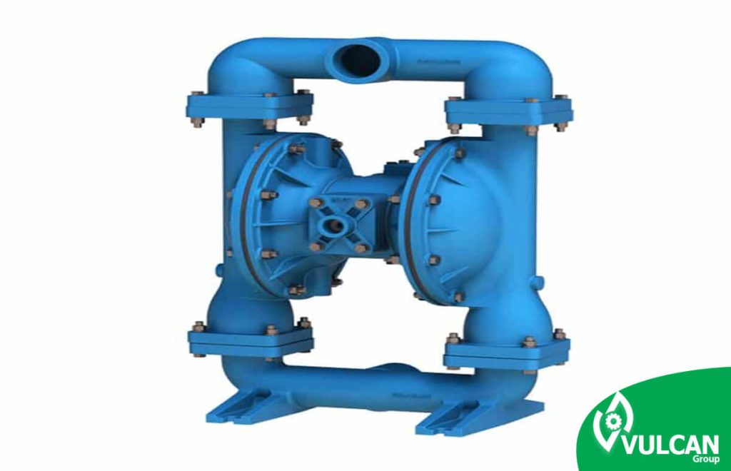
Diaphragm pumps are a combination of hydraulic fluid or pistons to control the movement of the diaphragm. Low-lift and low pressure pumps are designed to displace concentrated liquids and viscose, such as slurries or heavy oils. Teflon diaphragm pumps, for example, are used for industrial applications of wear and high pressure.
Diaphragm pumps are hydraulic or mechanically designed as positive displacement factors in pumps to create a variety of pressures and flow rates. They are actually pumps that use the top-down movement of a cup piece, with an elastic surface, to generate liquid flow. This surface located inside the pump is generally made of polyethylene tetrafluoroethylene (PTFE), Teflon, synthetic rubber or similar materials. When the surface is placed in the liquid, a certain pressure and displacement amount of the liquid is added. When removed from the liquid, it sinks into more fluid. The check valve is used in the diaphragm pump to prevent the return flow of fluid through the inlet valve.
Among the key features of diaphragm pumps is their ability to move dry for long periods without possible damage. This feature is due to the minimum amount of friction in the diaphragm pump, and more burnout is caused by greater fluid transmission than pump performance. Heavy duty pumps are designed to withstand highly concentrated and sometimes corrosive liquids, although suitable hose materials are necessary for such applications. Various plastics and metals (e.g. aluminum and stainless steel) are especially used as hoses for pumps.
A large number of industries use diaphragm pumps, which is a good sign of their diversity and durability. They have certain applications such as distillation, oil and feed transfers, and they are also common in cars and aircraft. They are even used in the biomedical industry, and are found in some artificial hearts as well. They are mainly used to move abrasive fluids such as cement or acids and chemicals.
Vertical Pumps
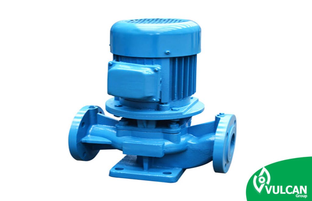
The use of flotation as a mineral separation method requires further development of slurry pumps. In early 1933 vertical pumps were developed in a Swedish flotation factory. This design was necessary because of the very complex circuits that existed in the factories.
Vertical slurry pumps are one of the strongest, hardest and most reliable pumps available, and therefore this series of pumps are preferred worldwide by most industries. These pumps are specifically designed for abrasive slurries and its important features include ease of maintenance.
In vertical pumps, parts in contact with fluid can be made of elastomers and hard alloys. For this reason, these pumps can be used in applications where corrosion is very high.
This type of pump, with a sturdy structure and special design, can work in harsh conditions with high performance. The vertical pump has an open tank with pump cover installed directly under the tank. Vertical slurry pumps are initially used to reduce slurry flow and … Floor pump is made. Two VT and VS slurry vertical pumps can both be used for floor pumping. The VT slurry pump consists of a pump and a pump tank attached to a unit. The pump cover is located under the tank, and connected through a hole at the bottom of the tank. The air, which is condensed in the center of the propeller simply moves upwards along the axis.
features vertical pumps:
- Use of high quality anti-abrasion materials
- Ability to use rubber coating instead of cast iron for some models according to operating conditions
- High quality and longevity
- Adjustable tolerances between propeller and shell
- Easy replacement and supply of worn parts
- Ability to install output at different angles
Main advantages of vertical pumps:
- Simple installation
- Protection of birings with double sealing to prevent slurry penetration
- Use of materials with excellent anti-wear properties and corrosion resistance
- Access to abrasion parts in a variety of materials
- Ability to replace parts under abrasion
- Availability of a range of butterflies
- Biring and sealing outside the pond
- Simple replacement of parts
- Different height
Types of vertical pumps:
VT Type: Vertical slurry pump tank type with metal or rubber parts
VF type: Vertical slurry pump floor type with metal or rubber parts
VS Type: Vertical slurry pump conical type with metal or rubber parts
VSHM type: vertical slurry pump conical type, hard operation with metal parts
VSHR type: vertical slurry pump conical type, hard operation with rubber parts
VSMM Type: Vertical slurry pump conical type, operation in mine with metal parts
Horizontal Pumps
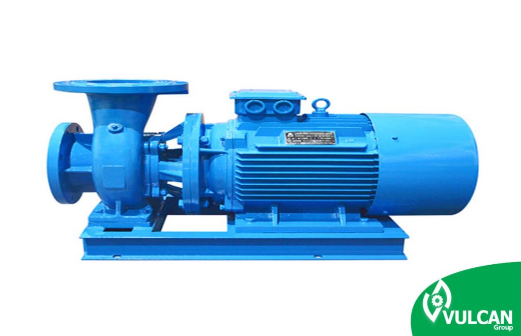
slurry pump is the foundation of all wet mineral processing. These pumps are used for a wide range of applications to move high concentration fluids containing solids, abrasives and silica, mineral concentrates, limestone slurries, coal transfer, dredging, waste containing fine and coarse particles and in gold, zinc, lead, copper and all kinds of mines and for onerous industrial applications. These pumps are exceptionally high efficiency and wear-under parts make them ideal for all applications that are the benchmark quality. Also, a wide range of sealing and configurations of these pumps tailor them for a variety of specific applications.
Horizontal slurry pumps are used
for a wide range of applications required for pumping abrasives and slurry materials. With a sturdy structure and special design, these types of slurry pumps can work in high performance under harsh conditions.
Applications:
- Iron ore slurry
- slurry Copper Concentrate
- slurry Coal
- Pulp with high abrasion
The main features of horizontal pumps are:
- Abrasion parts are made of high quality materials such as hard metal, rubber and corrosion resistant materials.
- Highest quality abrasion resistant elastomatic materials
- Application of hard metal or elastomatic parts according to operating conditions
- Accurate application at the best point of efficiency
- A special application is used for dredging applications, where horizontal pumps with “wet head” (and biring) are used. This is needed for certain arrangements for Biring.
Types of horizontal pumps
XM type: slurry pump with super hard operation with metal abrasion parts
XR type: Ultra-hard working slurry pump with rubber abrasion parts
HM Type: Hard-functioning slurry pump with metal parts
XR Type: Hard-functioning slurry pump with rubber parts
HG Type: Hard working sand pump
HP Type: High pressure pump with hard operation
HT Type: Hard-to-operate tunnel pump
MM Type: Mineral slurry pump with metal parts
MR Type: Inorganic slurry pump with rubber parts
Ordering material handling pumps and slurry pump liners
To place an order, just enter your details and contact number, our experts will contact you as soon as possible.
Related Content
How useful was this post?
Click on a star to rate it!
Average rating 5 / 5. Vote count: 2
No votes so far! Be the first to rate this post.